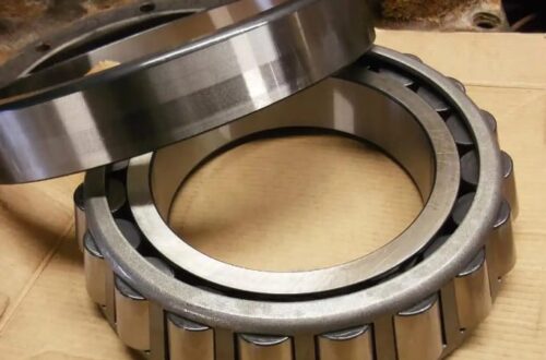
Today, I’d like to discuss a component that is critical to industrial equipment yet perhaps unfamiliar to the general public: the double-row tapered roller bearing. These bearings play an indispensable role in various types of heavy machinery and precision equipment; correctly identifying and selecting the right model is directly linked to the equipment’s operational performance.
Simply put, a double-row tapered roller bearing can be understood as a configuration where two single-row tapered roller bearings are combined “back-to-back” or “face-to-face.” This design allows the bearing to simultaneously withstand radial and axial loads from both directions, offering superior load-carrying capacity and greater rigidity. Compared to single-row bearings, they provide more stable rotational support within a limited space, making them widely used in applications such as automotive wheel hubs, machine tool spindles, and large gearboxes.
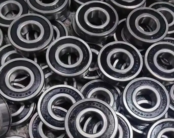
When we discuss bearing model numbers, we are essentially deciphering a standardized international “identity code.” This code typically consists of a combination of letters and numbers, with each segment conveying specific information. Below, I will outline the key points for interpreting these model numbers.
1. Composition of the Basic Model Number
A complete model number for a double-row tapered roller bearing usually consists of a basic designation and a supplementary designation. The basic designation is the core component, indicating the bearing’s type, dimension series, and inner diameter.
Type Designation: Typically begins with the digit “3,” signifying a “tapered roller bearing.” Double-row tapered roller bearings will have specific series identifiers based on this.
Dimension Series Designation: Follows immediately after the type designation and consists of two digits. It represents the bearing’s width series and diameter series—essentially determining its “bulkiness” (width/profile) and “height” (diameter). For instance, in common series like “32” or “33,” a higher number generally indicates larger dimensions and a higher load-carrying capacity.
Inner Diameter Designation: The last two digits of the basic designation; multiplying this value by 5 typically yields the bearing’s inner diameter (in millimeters). For example, if the inner diameter code is “20,” the inner diameter is approximately 100 millimeters. 2. Common Structural Configurations and Designations
Double-row tapered roller bearings primarily feature two classic arrangements, which are reflected in their part numbers.
“Back-to-back” configuration (DB configuration): The load lines of the two rows of tapered rollers diverge outwards. This structure offers high moment rigidity and effectively resists tilting moments; it is commonly used for fixed-end supports requiring high stiffness.
“Face-to-face” configuration (DF configuration): The load lines of the two rows of tapered rollers converge inwards. This structure accommodates axial displacement slightly better.
Information regarding these configurations is often indicated in the part number via suffixes or specific series designations. Representation methods may vary slightly between manufacturers, so it is essential to consult specific product catalogs.
3. Important Suffixes
Suffixes following the basic designation provide detailed information regarding the bearing’s internal structure, materials, precision class, internal clearance, and more. Several suffixes are particularly critical for double-row tapered roller bearings.
Clearance designation: Examples include /C1, /C2, /C3, /C4, and /C5, indicating the magnitude of internal radial clearance (ranging from tight to loose). The choice of clearance directly affects heat generation, noise levels, and service life; selection should be made carefully based on actual fit and operating conditions.
Precision class designation: Examples include /P0, /P6, /P5, and /P4 (with P0 usually omitted), representing the manufacturing precision grade. Higher precision classes offer superior rotational accuracy and higher limiting speeds, albeit at a higher cost. The P0 class is generally sufficient for standard operating conditions.
Cage designation: Indicates the cage material and structure—such as pressed steel, machined brass, or polymer cages. Cages made from different materials are suited to varying rotational speeds and lubrication conditions.
4. Considerations for Part Number Identification
Careful attention is required when identifying part numbers in practice. Standards systems differ across countries and manufacturers—encompassing ISO, JIS, DIN, and proprietary brand standards. While there is a trend toward convergence in mainstream part numbers, subtle differences may still exist. Model designations may include manufacturer-specific prefixes or suffixes indicating special designs, heat treatment processes, or lubricants. The most reliable method is to verify the specifications against the brand’s official product catalog.
5. Basic Principles of Model Selection
Selecting the right model is not merely a matter of simple matching; it is a process requiring comprehensive consideration. Key factors include the magnitude and direction of the radial and axial loads exerted on the bearing by the equipment; the required operating speed range; the operating environment (such as temperature and potential contamination); and spatial constraints regarding bearing dimensions. Typically, these parameters are calculated and determined by equipment design engineers. For maintenance or replacement purposes, strictly adhering to the original equipment manufacturer’s (OEM) specifications is the safest approach. If considering alternative models, one must carefully compare critical parameters such as dimensions and load-carrying capacity.
Understanding the designation system for double-row tapered roller bearings is like holding the key to effective equipment maintenance. It ensures accuracy during component replacement—preventing installation difficulties or premature failure caused by incorrect model selection—and enables more professional communication regarding requirements. Hopefully, this overview has provided a clearer understanding of this seemingly complex industrial component. The next time you encounter those strings of letters and numbers in your work, you will be better equipped to interpret the story they tell.