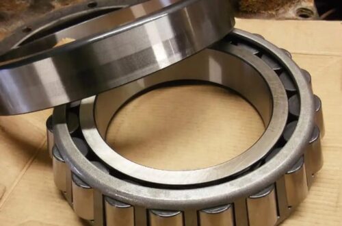
The single-row cylindrical roller bearing is a common type of rolling-element bearing characterized by cylindrical rolling elements that make line contact with the raceways; it is primarily designed to support radial loads. These bearings possess high radial load-carrying capacity and are suitable for applications involving heavy loads and shock loads. Understanding their dimensional parameters is fundamental to mechanical design, equipment maintenance, and component selection. Dimensions not only determine whether a bearing can be installed in the equipment but also directly influence its load-carrying capacity, speed limits, and service life.

Bearing dimensions are typically represented by a series of standardized numeric codes that contain key dimensional information. For single-row cylindrical roller bearings, the dimensional system centers on three basic dimensions—inner diameter, outer diameter, and width—while also encompassing structural dimensions related to load capacity, such as roller dimensions and the number of roller rows.
I. Basic Dimensional Parameters
Basic dimensions are those most directly indicated on engineering drawings and serve as the basis for installation fits.
1. Inner Diameter: Refers to the diameter of the bearing’s inner ring—the dimension that interfaces with the shaft. The inner diameter is one of the most critical parameters in a bearing’s designation. For most standard bearing designations, specific conversion rules apply to the inner diameter code. For instance, for bearings with an inner diameter of 20 mm or greater, multiplying the last two digits of the designation by 5 typically yields the nominal inner diameter in millimeters. The precision class of the inner diameter directly affects the nature of the fit between the bearing and the shaft—determining whether it is an interference fit or a clearance fit.
2. Outer Diameter: Refers to the diameter of the bearing’s outer ring—the dimension that interfaces with the bearing housing or machine casing. The outer diameter determines the installation space required within the equipment housing. The difference between the outer and inner diameters influences the thickness of the bearing’s cross-section and is related to the bearing’s rigidity.
3. Width: Refers to the bearing’s axial dimension—specifically, the width of the inner or outer ring. This dimension affects the axial space occupied by the bearing and is also correlated, to some extent, with radial load-carrying capacity; generally, a wider bearing can accommodate longer rollers or a greater number of rollers. II. Dimension Series Code
In a bearing designation, the number or letter combination preceding the bore diameter code typically indicates the dimension series. The dimension series reflects the various combinations of outside diameter and width for a given bore diameter and serves as the core classification within the bearing dimension system.
1. Diameter Series: Indicates the different outside diameter dimensions for a given bore diameter. Common codes include 2, 3, 4, etc.; generally, a higher number signifies a larger outside diameter, a thicker bearing cross-section, and a higher load-carrying capacity.
2. Width Series: Indicates the different width dimensions for a given bore diameter and diameter series. Common codes include 0, 1, 2, 3, etc.; generally, a higher number signifies a greater width.
For example, in the bearing designation “NU1024,” “10” is the dimension series code representing a specific combination of outside diameter and width, while “24” indicates a bore diameter of 120 mm. The dimension series code allows for the lookup of specific outside diameter and width values in standard dimension tables.
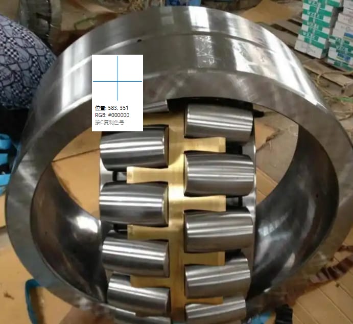
III. Relationship Between Structural Form and Dimensions
Single-row cylindrical roller bearings come in various structural forms, primarily distinguished by whether the inner and outer rings feature integral flanges and whether the bearing is separable. While these structural forms do not alter the basic overall dimensions, they do affect the bearing’s mounting dimensions and functional characteristics.
1. NU Type: The outer ring has two integral flanges, while the inner ring has none. The bearing is separable, allowing the inner ring and the roller-and-cage assembly to be mounted independently. This structure permits slight axial displacement of the shaft relative to the housing in both directions and is commonly used at the non-locating end.
2. NJ Type: The outer ring has two integral flanges, while the inner ring has one. It is also separable. It can withstand axial loads in one direction and is commonly used for axial location.
3. N Type: The outer ring has no integral flanges, while the inner ring has two. It is separable.
4. NF Type: The outer ring has one integral flange, while the inner ring has two. It is separable.
For bearings of different structural forms, the height and position of the inner or outer ring flanges are critical mounting and functional dimensions; these factors must be carefully considered when designing the heights of shaft shoulders and housing shoulders. IV. Precision Classes and Dimensional Tolerances
Bearing dimensions are not fixed theoretical values but fall within an allowable range of variation known as tolerance. Precision classes define the width of these tolerance zones.
1. Dimensional Precision: Includes allowable deviations for inner diameter, outer diameter, and width. Bearings with higher precision classes exhibit smaller deviations between actual and nominal dimensions, ensuring more precise rotation and reduced runout.
2. Rotational Precision: Includes radial runout and axial runout (face runout) of the inner and outer rings. This directly affects the rotational stability of the equipment’s spindle.
Common precision classes, ranging from low to high, include P0, P6, P5, P4, and P2. P0 is the standard general-purpose class. Higher precision classes demand superior manufacturing processes and stricter dimensional control.
V. Cage and Roller Parameters
Although not classified as mounting fit dimensions, the dimensional parameters of rollers and cages directly influence bearing performance.
1. Roller Diameter and Length: Roller dimensions determine the total contact area of the bearing’s rolling elements. For a given set of external bearing dimensions, using rollers with larger diameters or greater lengths can enhance radial load-carrying capacity, though this may impact the limiting speed.
2. Number of Rollers: Increasing the number of rollers can boost load-carrying capacity, provided the spacing between cage pockets allows for it. The number of rollers is typically closely linked to the cage design.
3. Cage Type: Common types include pressed steel cages, solid brass cages, and polymer cages. Cage design determines roller spacing and guidance methods, making it a critical component influencing lubrication and high-speed performance.
VI. Dimensional Measurement and Verification
In practical applications, accurately measuring bearing dimensions is a prerequisite for ensuring installation quality.
1. Measuring Tools: Typically, an outside micrometer is used for the outer diameter, an inside micrometer or bore gauge for the inner diameter, and a dial indicator or height gauge combined with a surface plate for the width. Measurements should be taken at multiple locations to check for out-of-roundness and taper. 2. Measurement Environment and Temperature: Precision measurements should be conducted under constant-temperature conditions to prevent thermal expansion or contraction—caused by temperature fluctuations—from affecting the results. Before measurement, both the bearing and the measuring tools should be placed in the same environment for a sufficient period to ensure temperature equalization.
3. Dimensional Recording: For critical equipment or high-precision applications, actual measured values of key bearing dimensions should be recorded to serve as a reference for installation and subsequent maintenance.
VII. Factors to Consider for Dimensional Selection
When selecting bearing dimensions, one must not merely consider the suitability of the installation space; a comprehensive evaluation is required.
1. Load Conditions: The magnitude of the radial load is the primary factor determining the bearing’s dimension series (particularly the diameter series). Heavy loads necessitate bearings with larger outside diameters, greater widths, and larger rolling elements.
2. Rotational Speed Requirements: For high-speed applications, the bearing’s limiting speed must be considered. Sometimes, to meet speed requirements, it may be necessary to select a bearing that is slightly smaller in size but possesses a higher precision class and an optimized cage design.
3. Installation Space Constraints: Equipment design compactness imposes strict constraints; one must select a bearing of appropriate size within the available space.
4. Rigidity Requirements: For applications demanding high rigidity—such as machine tool spindles—selecting bearings with thicker cross-sections (larger diameter series) helps enhance system rigidity.
5. Expected Service Life: Based on the equipment’s design life requirements, life calculations should be performed to verify whether the selected bearing size meets the necessary service life.
The dimensions of a single-row cylindrical roller bearing constitute a systematic set of parameters. These range from basic specifications—such as inner diameter, outer diameter, and width—to dimension series embedded in the model designation, as well as various dimensional tolerances and internal parameters related to structure and precision. Together, these factors define the bearing’s physical form and performance limits. Correctly understanding, measuring, and applying this dimensional data is fundamental to ensuring the bearing operates reliably throughout its service life. In engineering practice, dimensional verification and selection should always be conducted in accordance with the equipment manufacturer’s technical manual or recognized international and domestic standards.